Spanish Version
OBJECTIVES:
- To become familiar with the components of microscopes commonly used by plant pathologists.
- To become familiar with the proper care and maintenance of microscopes.
- To learn the steps for proper focusing on material and observation with a microscope.
- To learn how to determine the magnification of materials being observed using a microscope.
INTRODUCTION:
Proper microscope use is one of the most important skills that a beginning plant pathology student can learn. Microscopes were developed during the late 17th century and continue to be important in identifying fungi and other causal agents of plant diseases. Although microscopes often are introduced to students early in their science classes, students frequently do not learn how to use and care for microscopes. In fact, in many classes microscopes are set up by someone else and students are told to not change anything other than possibly the focus. This teaching aid provides basic information and instructions on how to set up, use, and care for microscopes, essential skills for plant pathologists.
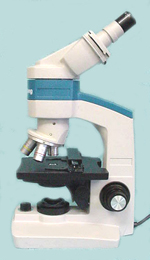 |
Figure 1. Click on images to see labeled parts.
|
 |
|
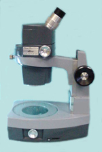
Figure 2. Click on images to see labeled parts. |
Two types of light microscopes commonly are used in introductory plant pathology courses. These microscopes are the compound microscope (Figure 1) and the dissecting or stereo-microscope (Figure 2). Dissecting microscopes are commonly used for the observation of larger objects and generally have magnifications of less than 100x. The light source used with the dissecting microscope can be located above the microscope stage, or the light may be transmitted through the base of the stage. Compound microscopes are used for the observation of smaller specimens which are placed on microscope slides and topped with a cover slip. Such specimens should be transparent or translucent because light must be transmitted through the specimen to reach the lens of the microscope. Magnifications commonly found on compound microscopes are between 10x and 1000x.
Components of this exercise include:
- Parts of microscopes
- How to move and transport microscopes properly
- Determination of magnification
- Adjustment of eyepieces
- Placement and focusing of specimen slide
- Orientation of materials on a slide
CLICK HERE FOR INSTRUCTOR'S NOTES.
MATERIALS:
- Compound microscope
- Dissecting microscope and light source
- Microscope slides and cover slips
- Scissors
- Dropper bottle with water
- Immersion oil
- Letter "e's" typed in six point font and printed onto a white piece of paper which is then reduced 50% onto a clear transparency which can be cut into individual "e's" for each student (final size of "e" is 0.6 x 0.45 mm)
PROCEDURES:
Parts of Microscopes
You should familiarize yourself with the different parts of the microscopes before using them because you will need to know where the different parts can be found on your microscopes. Some of these components may be located in slightly different positions on different models of microscopes. Take a few minutes to study Figures 1 and 2 before proceeding. The major components of the compound and dissecting microscopes and their purposes are outlined in Table 1. Note the differences between the two types of microscopes before continuing.
Q. What components are present on the compound microscope that are not present on the dissecting microscope based on the Figures 1 and 2?
Q. What components are present on the dissecting microscope that are not present on the compound microscope?
Table 1. Major components of microscopes and their general description and purpose.
|
Component |
Description | |
| Base | Metal or plastic part on which microscope rests |
| Arm | Somewhat C shaped pillar arising from base that supports the stage and ocular components |
| Stage | Flat platform attached to lower portion of arm on which slides or samples are placed |
Condenser or Iris
Diaphragm lever | Lever beneath opening in the stage, consists of a shutter-like group of metal leaves which regulate the amount of light coming through the slide on the stage |
Condenser
| Not present on all microscopes - collects illuminator light rays and focuses them - increases the resolution, enhances contrast of sample |
| Condenser adjustment knob | Raises and lowers the condenser |
| Tube/Barrel | Cylindrical/vertical part attached at the top of arm for support of optical system |
| Turret | Revolving plate which bears the objective lens, attached at lower end of tube, can be turned to change the objective lens |
| Coarse Focus | Larger knob which moves the tube up or down rapidly to get the sample into coarse focus |
| Fine Focus | Smaller knob which moves the tube through short distances slowly and is used to get the sample into sharp focus |
| Transformer or illuminator | Controls the amount of light transferred to the sample |
| Eyepiece (ocular lens) | Removable, short metal tube that contains lens that fit into the top of the tube - generally 10-15x magnification |
| Eyepiece Focusing Ring | Adjustment used to compensate for differences between eyes |
| Objective Lens | Small metal tubes screwed into the turret which increase the magnification of the sample. (often referred to as just objective) |
| Mirror | Used to reflect light through a sample |
| Mirror Axle | Used to adjust mirror to reflect light through a sample |
| Auxiliary Lens | Also referred to as supplemental lens, may be found on dissecting microscopes at the base of the objective cover or tube |
How to Move and Transport Microscopes Properly
Microscopes are often stored in cabinets when they are not in use and must be removed in order to use them. To remove microscopes from the storage area, place one hand completely around the arm, and then place your other hand underneath the microscope base. Always carry the microscope in an upright position. Carrying in any other way may allow parts to fall from the microscope. Use care to ensure that electrical cords are not entangled with those of other microscopes. Place microscope on a clean area of the desk or laboratory bench.
Light sources are required for most microscopic observations. The cord for the light should be plugged into a suitable outlet. Dissecting microscope lights are often a unit separate from the microscope. Such lights may be attached to the arm to illuminate the stage from above the sample. Alternatively, light sources may be placed next to the stage at the level of the sample, or below the stage.
Q. Note the differences between your compound microscope and the compound microscope illustrated in Figure 1. If components are in different locations, these altered locations should be noted below.
Q. Is your dissecting microscope different from the one illustrated in Figure 2? If so, please note differences below for your dissecting microscope.
Determination of Magnification
Magnification is a measure of the ability of the microscope to enlarge an image. Resolution is a measure of the ability of the microscope to separate different points of the image. Determining magnification is vital when comparing the sizes of different objects being viewed with a microscope. Note the magnification of the eyepieces and the different objectives on your microscope. The magnification is printed or etched on the side of the objective and on the side or top of the eyepiece. This magnification is shown as a number followed by an x (e.g. 15x). Dissecting microscopes may have an additional lens (referred to as an auxiliary or supplemental lens) on the base of the objective cover in order to increase magnification. Note if your dissecting microscope has such an auxiliary lens. Dissecting microscopes also may have a magnification knob which changes the magnification when turned. Note the markings on or near this knob that are used to determine the magnification.
Compound microscopes often have objectives which are designed strictly for use with immersion oil. These objectives are identified by having the word "oil" engraved on the side, near the number stating the magnification of the objective. Oil objectives cannot be used without immersion oil. Other objectives cannot be used with oil and can be damaged if inadvertently immersed in oil. The use of an oil immersion lens is essential when viewing structures less than 10 µm in size. For example, magnification requiring an oil immersion lens is necessary to determine the shape of an individual bacterium. Oil immersion does not increase the magnification of the lens, but it improves the resolution or sharpness of the image produced by the objective. When light passes through any material to another, such as from glass to air, the light is refracted or bent. Light of different wavelengths bend at different angles. Such refraction results in distortion which can be significant at higher magnifications. By putting a drop of immersion oil, which has the same refractive index as glass, between the 100x objective and your slide you significantly reduce the light scattering that would otherwise occur, thereby increasing the resolution of the image.
To determine the magnification of any image, you will need to multiply the eyepiece magnification by the objective magnification. If an auxiliary lens is present on a dissecting microscope, its magnification must be multiplied times the objective and eyepiece magnifications. It is important to note the magnification on all drawings so that you can compare the relative sizes of images that you observe at various times. In many cases you will need to use two or more different magnifications to view all the details of a sample.
Q. What is the magnification of the eyepieces on your dissecting and compound microscopes?
Dissecting _______________
Compound _______________
Q. What are the magnifications of objectives of your compound microscope? ____________
Q. Does your microscope have an oil immersion lens?______
Q. What is its magnification? ___________
Q. What is the maximum magnification which you can obtain with your compound microscope?
With use of oil? ____________________________
Q. Without use of oil? ___________________________
 |
|
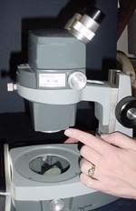
Figure 3. |
Q. Does your dissecting microscope have an auxiliary or supplemental magnification lens at the bottom of the objective cover (Figure 3)? _____________________________
Q. If so what is its magnification factor? _______________________________
 |
|
Figure 4. |
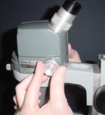
Q. What is the minimum and maximum magnification that you can obtain when using the adjustment associated with your magnification knob located on the side of your dissecting microscope (Figure 4)? __________________________
Q. What is the maximum magnification available when using your dissecting microscope?
Q. Remember to include the auxiliary or supplemental lens factor if present on your microscope and the maximum for the adjustable magnification knob and eyepieces. ______________________
 |
|
Figure 5A. |
 |
|
Figure 5B. |
Adjustment of Eyepieces
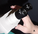
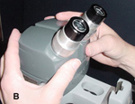
Several adjustments are necessary before looking at specimens. On binocular microscopes (microscopes with two eyepieces) the distance between eyepieces should be adjusted so that you can look through both eyepieces easily at the same time and see a single image. There are several different methods of adjusting this distance depending on the microscope being used. In some microscopes there is a knob at the top of the microscope between the eyepieces that adjusts the eyepiece distance (Figure 5A). Other microscopes are adjusted by pushing on the eyepieces (Figure 5B). This adjustment is specific to each person so minor adjustments may be required when one person looks through a microscope set up by another person. Make this adjustment before continuing. Adjusting for differences between a person's eyes using the focusing sleeve on left or both eyepieces is another important adjustment to prevent discomfort and fatigue of the microscope user. The procedure for making this adjustment follows the initial focusing since a specimen has to be observable for making the adjustments.
Placement and Focusing of Specimen Slide
Specimen slide placement and focusing are the first techniques that need to be considered. To proceed, obtain an "e" provided by the instructor. After focusing the "e" will be used to illustrate the movement and orientation of materials on the slide.
- Cut out around an "e" approximately 0.5 cm.
- Place a drop of water on the slide and put a mark on one of the long sides of the slide.
- Place your "e" on a slide so the top of the "e" is toward the mark on the slide.
- Obtain a cover slip and pick it up by the edges. Place one edge on the slide next to your "e". Slowly lower the other edge of the cover slip slowly over the "e" so that the water will spread out underneath the cover slip. Soak up any extra water with blotting paper or paper towel. The "e" should now remain in position on the slide as you observe it under the microscope.
- Make sure that your compound microscope is in a position where you can easily look through the eyepieces - adjust chair height and eyepiece width as needed. Make sure that light source (illuminator) is plugged in and turned on. Use care to put the electrical cord in a position where someone will not trip over it or where you can possibly pull the microscope off the table accidentally.
 |
|
Figure 6. |
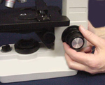
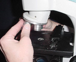
- Raise the tube using the coarse adjustment knob to provide greater access to the stage (Figure 6). (In some cases the stage moves instead of the tube.)
 |
|
Figure 7. |
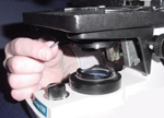
- Rotate the turret so that you are using the lowest power objective (usually 4x or 10x) (Figure 7).
 |
|
Figure 8. |
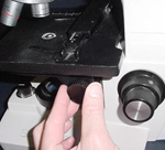
- Using the lever of the condenser, open the condenser diaphragm approximately half way (Figure 8).
- Place the slide on the stage with the mark on the slide on the side away from you. Also place the "e" directly above the center of the condenser (located underneath the stage) by moving the slide as needed.
 |
|
Figure 9. |
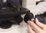
- Raise the microscope condenser by means of the condenser knob (if available) until the top of the condenser is approximately the thickness of a piece of paper below the slide (Figure 9).
 |
|
Figure 10. |
- Rotate the fine focus adjustment knob so that it is approximately at its midpoint (Figure 10).
- Rotate the coarse adjustment knob (Figure 6) to lower the tube until the slide is almost touching the objective or the positive stop is reached. Be sure to observe from the side of the microscope while you lower the tube. You do not want to force the objective into the slide. This could break the slide or more importantly damage the objective.
- While using your right eye and eyepiece slowly turn the coarse adjustment knob to raise the tube until the "e" comes into focus. Adjust the coarse adjustment to get the best possible focus.
- Use the fine focus knob to sharpen the image as much as possible (Figure 10). If more than one person is using the microscope, each person likely will need to adjust the fine focus to sharpen the image.
- Without disturbing the focusing knob, look at the "e" using the left eye only, using only the left eyepiece. Turn the eyepiece focusing ring of the left eyepiece counterclockwise until the "e" is out of focus. Still using the left eye only, turn the eyepiece focusing ring clockwise until sharp focus is obtained. This adjustment will reduce eye fatigue.
- You should now proceed to make observations of your sample.
Orientation of Materials on a Slide
Making accurate drawings of your observations can be extremely important. These drawings will be especially important when you are making comparisons of drawings made at different times. It may be advantageous to draw a circle representing your field of view and then add a grid. The circle and grid will assist you in drawing details in the correct place and size. Make sure to note the magnification at the bottom of your circle.
Q. Draw what you observe. Note the top of the "e" as you look through the microscope. How does the position of the top of the "e" compare with what you observe when you are not looking through the microscope? Are they different? Is this important?
Q. If you need to look at the material on the left side of your image which way do you need to move the slide? _______________________
Q. If you need to look at the material at the top of your image which way do you need to move the slide? ___________________________
Q. Why is this important?
- To increase the magnification you should proceed as follows: Make sure that your sample is in focus with lower power objective.
- While observing the objective to make sure it clears the slide holder and slide safely, turn the turret containing objectives to next higher power objective and make sure it is in proper position over the sample. (Most turrets have positions which the objectives will snap into indicating that they are in the correct position. If the light is not observable or the circle of light is not centered make sure the turret is in the correct position.)
- Use the fine focus to sharpen the image. You should not have to use the coarse adjustment.
- If you need to increase the magnification further repeat steps 17-19.
 |
|
Figure 11. |
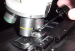
- If the oil immersion objective is needed, you will need to add a drop of immersion oil to the slide. (Mineral oil and other oils should not be used.) When you turn the turret stop halfway between the non-oil immersion objective and the oil immersion objective (Figure 11).
- Add a drop of immersion oil on top of the slide in the center of light observed coming through the slide.
- Turn the turret so the oil immersion objective is directly over the slide. The drop of oil should form an oil bridge between the objective and the slide.
- Use the fine focus to obtain the sharpest image.
- You may need to adjust the condenser to increase/decrease the amount of light coming through the condenser using condenser level (Figure 8).
-
Special Note: Be sure not to get oil on other objectives because it can damage them.
- When you finish with an oil immersion objective raise the tube and wipe oil off the objective immediately and remove the slide with oil. Clean oil off slides if they are to be used further or are permanent laboratory slides. Objectives may be cleaned with lens paper and distilled water. Use only lens paper for cleaning objective because other materials (Kimwipes, paper towels, etc.) will damage them.
- Any time you are ready to remove a slide, always raise the tube prior to removing the slide to ensure that you don't inadvertently damage an objective by contacting it with the slide.
Q. Note the differences that you can see within the "e" when you switch to higher magnification below.
Use of Dissecting Microscope
There are several differences between using a compound microscope and using a dissecting microscope (sometimes referred to as a stereo-microscope because it is like two microscopes set to focus on one point providing a 3-dimensional or stereoscopic view of the specimen). Generally most dissecting microscopes do not have a fine adjustment knob. The light source (illuminator) may also be separate and it may be mounted on the arm, below the stage plate, or at the level of the stage. Your instructor will give you specific instructions related to your microscope. Many dissecting microscopes do not have separate objectives to increase the magnification but they have a magnification knob that can be turned to increase or decrease magnification. Note: Some dissecting microscopes also have an auxiliary or supplemental lens on the bottom of the objective cover or body. If this lens is present, it must be included in the determination of magnification.
Samples are placed on the stage plate and are moved by hand. Light can be transmitted through the slide by adjusting the mirror below the sample or the sample may be viewed with the light coming from above. When viewing the sample with the light coming from below you may need to adjust the mirror so that the light is properly adjusted for viewing. Use the steps as outlined below, ignoring those that do not apply to your microscope.
 |
|
Figure 12. |
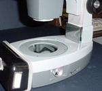
To view the "e" it is best to have the light coming from below the sample (Figure 12). Follow Steps 1-4 for the compound microscope as appropriate.
- Place the slide with the "e" on the stage with the top of the "e" away from you (the mark on the slide should be away from you).
- Adjust the mirror axis (Figure 12) to get the light transmitted through the sample, then use the focusing knob to bring the "e" into focus.
- Draw the orientation of the "e" within a circle.
Q. Are there any differences from what you observed earlier with the compound microscope? If so, what are they?
- Determine the magnification of your sample using the following formula. You may need to estimate the magnification setting on the magnification knob. There is a line indicating the point at which to estimate the magnification associated with the magnification knob.
Q. Eyepiece X Auxiliary Lens X Magnification Knob Setting = Total Magnification
________ X ________ X ________ = __________
- When you move materials to the left or away from you which way does the image that you observe through the microscope move?
Q. Is this different or the same as what you observed with the compound microscope?
Q. When would you want to use a light source that is shining directly on the sample (light positioned above the sample)?
Q. What is the advantage of this?
After you have finished using your microscope for the day, care should be taken in properly storing it. Make sure that objectives are clean and slides are removed. Turn off all lights. Unplug electrical cords and loosely wrap around the base. Remove lights that are associated with dissecting microscopes. Place all microscopes and lights carefully back into their proper storage area. Instructors may provide further instructions as appropriate.
Get the Answers to the Exercise Questions
IMPORTANT NOTES
If you have any problems, ask your instructor for assistance. Do not disassemble microscopes.
USEFUL REFERENCES
http://www.microscopyu.com - Web site for Nikon Microscopy - contains feature articles and tutorials as well as microscopic images. It also includes technical developments related to new techniques and microscopes.
